The ageing of the GRTgaz system means that more and more inspections are required and there are many special cases. Indeed, these particular cases constitute a major part of the inspection problems reported by GRTgaz's Operations Department to the Technical Department and to RICE. A multi-functional team has been working on the IPOG (Inspection Par Ondes Guidées) project for more than two years and in particular on the development of the guided wave technique to inspect non-accessible pipes, which constitute the majority of the particular cases reported. The project was the winner of the GRTgaz 2021 innovation challenge.A technique adapted to structures located in concrete walls|Easy to implement|Use cases identified and tested by mock-upsInspection techniques using instrumented pigs or electrical surface measurements are often not well adapted to the inspection of non-accessible structures, such as those located in concrete walls. Currently, only the destruction of concrete walls allows access to apply conventional control techniques. This is a costly and risky operation that ends with the reconstruction of the concrete mass. Tests carried out on a compression station with the IPOG technique have made it possible to avoid destroying the concrete wall, at a cost 22 times lower, and with a speed of intervention of the order of 100 times greater than the conventional method by destruction of the mass. For a station that can include about 100 concrete sails, the savings linked to the use of the "IPOG" technique are strategic.|The IPOG technique is one of the techniques recognized by the GESIP guide (Groupe d'Étude de Sécurité et des Industries Pétrolières) and allows the inspection of up to 80 meters of pipe in one shot. The distance inspected depends mainly on the nature of the coating and the configuration of the structure (presence of elbows, tees, ...).
This technique is based on the propagation of ultrasonic waves guided by the thickness along the pipe, thus allowing to detect remotely any variation in thickness, including metal losses (see diagram below).
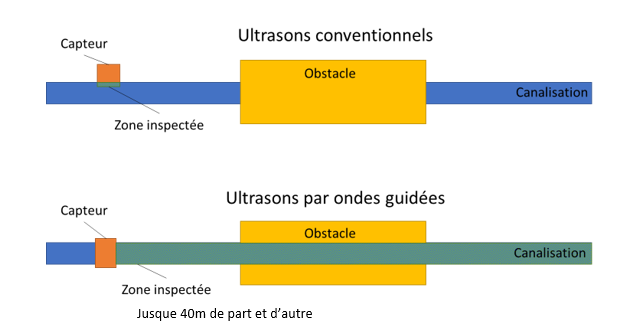
Figure 1: Comparison of guided wave and conventional ultrasound inspection distances
The installation is easy since it is enough to install a ring of sensors around the pipe and to connect it to the module which emits the waves and records the reflection of the signal.
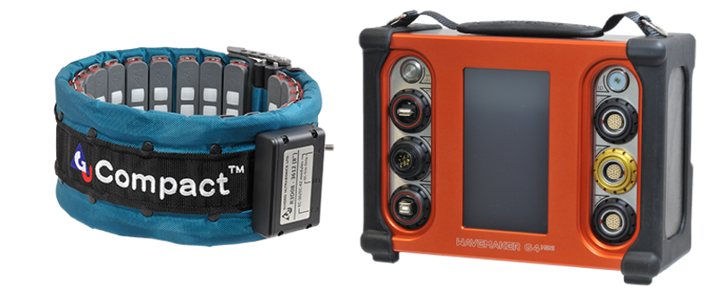
Figure 2 : material used for guided waves
|Tests are being conducted to validate the technique on several configurations. A mock-up simulating an under-sheath passage was created with a number of metal losses of different dimensions. A guided wave inspection was then performed and the comparison of the results obtained with the real characteristics of the machined defects shows a good correlation, which validates the technique for these use cases.
A second model with machined defects and simulating a floor inlet/outlet with the associated type of coating was also tested at RICE. The results are also convincing, especially on defects located at the air/ground interface, where the corrosion phenomenon is more important.
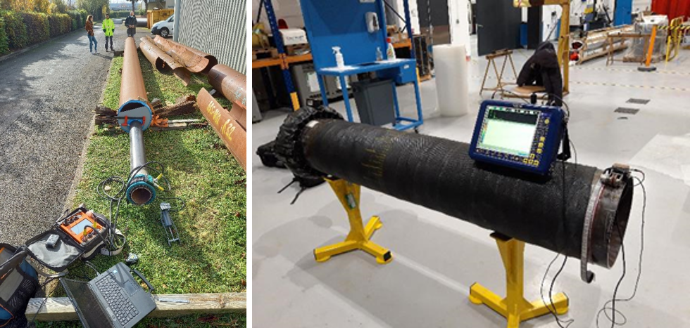
Figure 3: Sheath model (left) and soil inlet / outlet (right)
In the absence of alternative solutions, various field tests were also carried out to validate the implementation of the technique on several configurations: concrete vaults, sleeve crossings, aerial crossings, support piles.
The next step of the project is to continue to strengthen the REX by testing the technique on more real use cases on the network, which will then allow the realization of a flowchart with the limits of the technique per use case. The long-term objective is to integrate guided waves in the panel of inspection tools available to GRTgaz and thus propose a validated technique for the identified use cases.||||||||||||


